|
|
|
||
|
Advice_ FAQ _Media _Resources _Tech Help _Tech Info _Forum _Search _Shop _Contact |
|||
|
|
|
||
|
Advice_ FAQ _Media _Resources _Tech Help _Tech Info _Forum _Search _Shop _Contact |
|||
|
Door Lock Timer Diagnosis and Repair |
|
By Robert Bowen, edited by Wes Stinson If
you have a 1990 to 1994 or so Nissan product (Nissan or
Infiniti), and your power door locks are acting strangely, the
problem is most likely caused by the door lock timer. The most
common symptoms of a flaky door lock timer are one or more of
the following: 1.Doors
don’t lock with the switch or driver’s lock knob 2.Door
locking and unlocking is intermittent 3.Doors
lock as soon as you unlock them 4.Doors
lock when you turn the ignition on, or at other weird times Your
door lock timer is NOT the problem if only one door doesn’t
lock, or locks at the wrong time. The door lock timer only sends
out one unlock pulse to all the doors except for some later cars
that have driver’s door priority, where the driver’s door
unlocks first. If
the doors won’t lock with the key in the ignition, that
isn’t a problem, it’s a feature of 90s Nissan door locks.
Also, if the driver’s door lock knob works, but the lock
switch doesn’t, it might be the lock switch rather than the
timer (although the timer is more likely to fail than the
switch). Each
car has the door lock timer in a different place: 90-93
Q45 - under the center console 93-94
J30 - under the driver’s side dash 90-94
Pathfinder – in left rear trunk area 90-94
Maxima – under driver’s side dash If
you have any others, let me know. The
door lock timer is readily available from any Nissan or Infiniti
dealer for between $65 and $80. The easiest way to repair the
problem is to order a new timer and install it. If
you’re handy with a soldering iron, or you want to learn,
there is a cheaper way. The electronics and relay contacts
inside the timers are good for many years. The problem is some
of the soldered contacts between the circuit board and relay.
This happens because when the timers were made, they were
soldered by machine. Some of the parts have terminals that are
larger, and don’t heat up as well. This leads to poor solder
connections that should have been caught in quality control, but
were not. Ten or 15 years down the line, these poor solder
connections vibrate loose and corrode, which leads to
intermittently bad connections and all of the symptoms listed
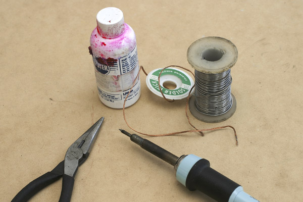
above. To
repair the timer you need a soldering iron, some electronic
solder (rosin core), soldering flux and a “solder sucker” or
solder braid.
If
you’ve never used solder braid to desolder before, practice on
a scrap circuit board until you understand how to use it to
remove solder. Here’s a link to desoldering technique: http://www.sas.org/E-Bulletin/2002-05-31/labNotes2/body.html If
you’re a little unclear of solder technique, it wouldn’t
hurt to read the following: http://www.aaroncake.net/electronics/solder.htm The
tools and supplies to repair the timer will actually cost about
half of what it would cost to buy a new timer, and you’ll both
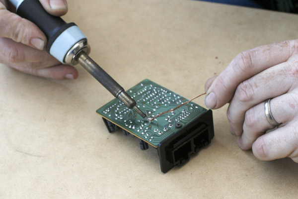
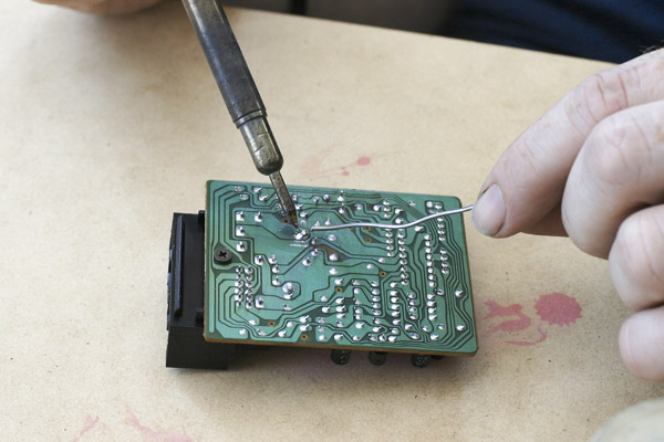
keep the tools and learn a new skill. Resoldering
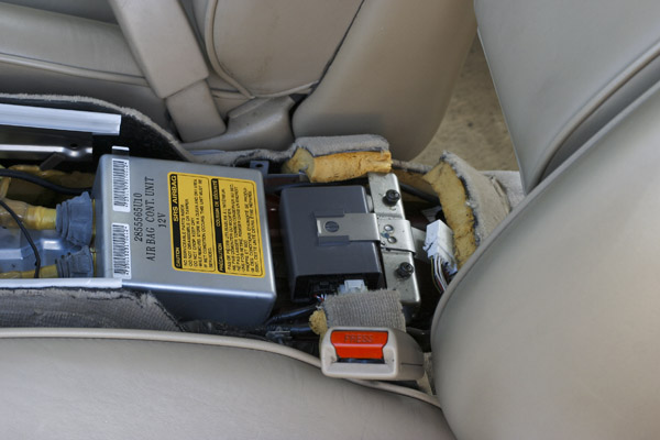
a timer: Remove
the timer. Dig
the timer out of wherever it is hiding in your particular car.
In this picture you can see where it is in the early Q45.
Don’t drop anything on the airbag control module. Unplug it
and remove it from its bracket.
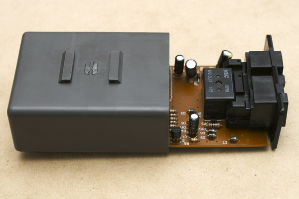
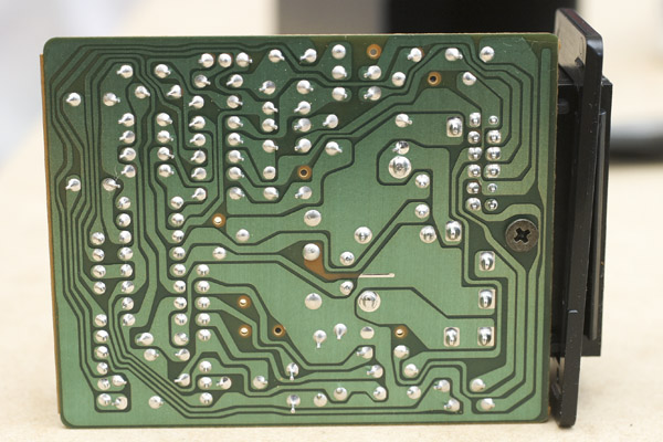
Disassemble
it. Pull
the case off of the circuit board. There are small tabs on the
end with the female plug that are easy to bend out of the way.
Once
you have it apart, you can see the components on the top of the
board. The black box is a relay, and it has the heavy terminals
that usually fail.
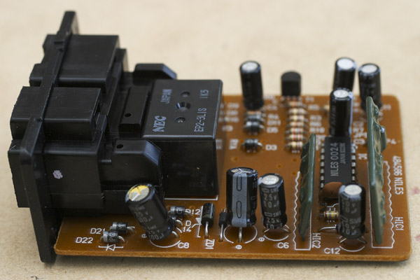
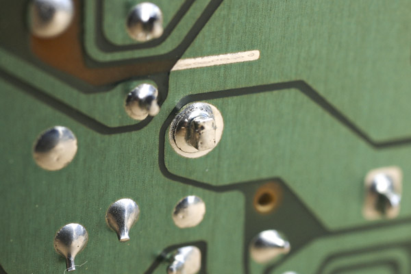
Check
for bad solder connections. Flip
the board over and check all of the solder connections,
especially those for the relay.
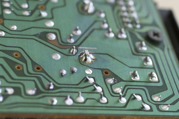
Check
out this closeup of what a bad connection looks like.
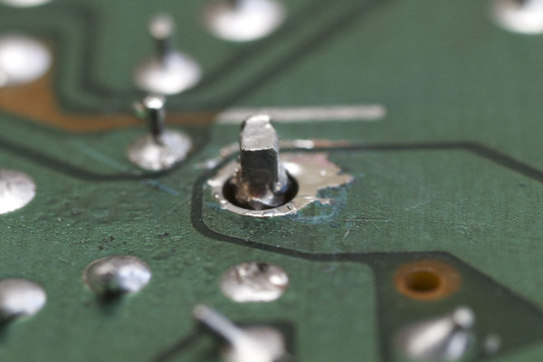
Desolder
the bad connections. Remove
the solder from the bad solder connection. If you’re
ambitious, re-do all of the relay connections.
The
cleaned connection should look like this.
Resolder the connections Apply
the flux to the terminal and PCB pad. Then resolder the part to
the board. Look carefully for signs of a cold solder joint,
since you don’t want to do this again.
It
should look like this when you’re done. (or better- mine has
too much solder to be perfect).
Reinstall the PCB and timer module Put
the timer back where it came from and enjoy your newly working
locks.
|
|
This web site is the intellectual property of Jesda Gulati and Wes Stinson. |